


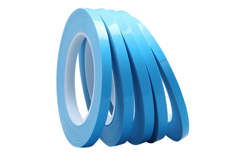
Related Product

Share Article
Material Selection Guide
Selection of thermal interface materials (TIMs)
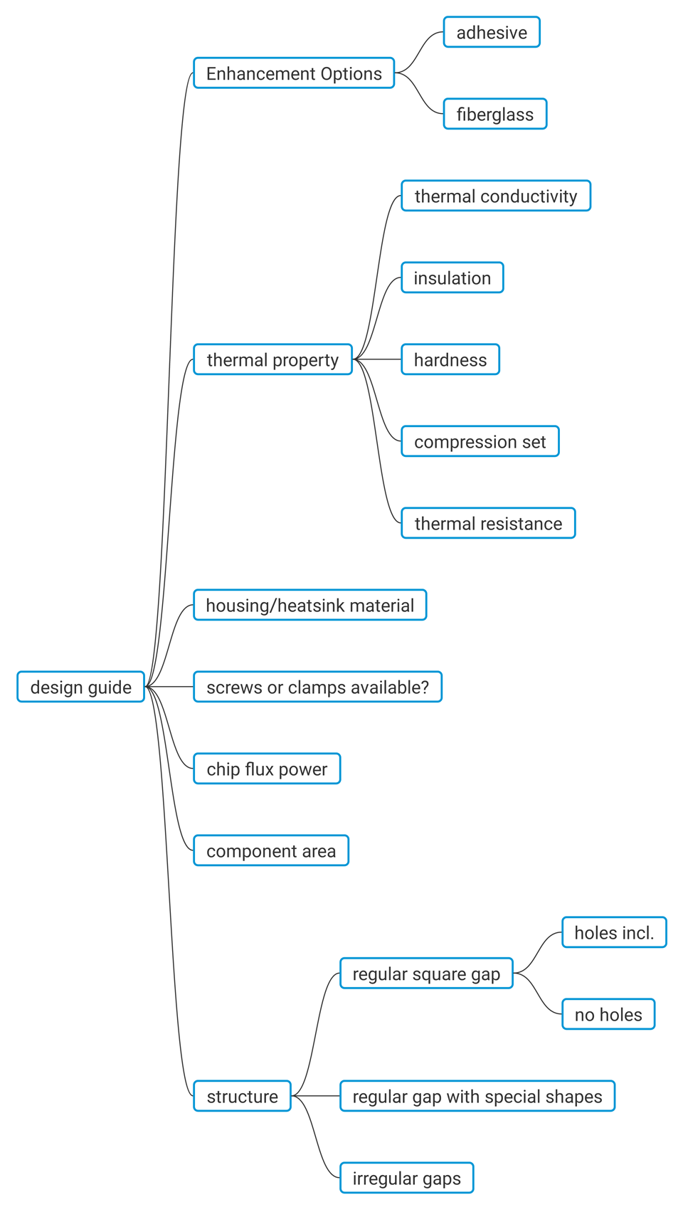
Selection of thermal interface materials (TIMs) is a lousy & complex work for mechanical engineers as they'll find thousands of options available in the market and they may get lost sometimes. Today, you'll get to find some tips from our design guide here and hope that'll be useful when you feel confused.
When people talk about TIMs, you'll think of several key points right away, such as Thermal Conductivity, Insulation, Hardness, Compression Set & thermal resistance. These are all fundamental properties we care about the most. But is that all? We should say not finished yet. In real applications, it's more complicated than expected as you have to take more factors into account, like the housing / heatsink materials, chip flux power, component area etc.
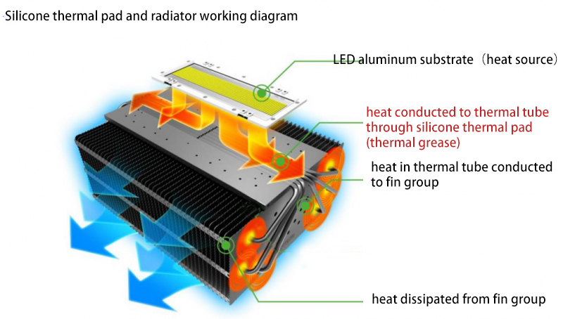
Firstly, let's start from the principle theory of Fourier's law and you'll get to know some insights of how it works from the inside out.
Fourier’s Law:
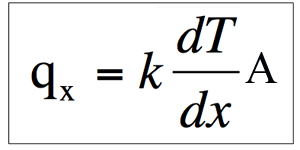
Where the vector Q is the heat flux (W/m2) in the positive x-direction, dT/dx is the (negative) temperature gradient (K/m) in the direction of heat flow (i.e., conduction occurs in the direction of decreasing temperature and the minus sign confirms this thermodynamic axiom) and the proportionality constant K is the Thermal Conductivity of the material (W/m.K), and A represents the contact area.
Fourier's Law thus provides the definition of thermal conductivity and forms the basis of many methods of determining its value. Fourier's Law, as the basic rate equation of the conduction process, when combined with the principle of conservation of energy, also forms the basis for the analysis of most Conduction problems.
Four Properties Need to Take Care
From this equation, it's clearly that thermal conductivity would have great impact on the heat flow rate if all the rest conditions are settled in the same level. When selecting the thermal pads, here are the other four properties need to take care as following.
Dielectric Insulation / Breakdown Voltage
It’s critical for high power applications to avoid the short-circuit and components failure.
Hardness
Generally, softer materials have better compression rate & gap filling conformability and thus get lower thermal resistance. While, you should also consider about the assembly capability as it’ll be difficult to remove off the liner and get distorted to be out of tolerance or even cannot fit to your designs perfectly.
Compression Set
As above, it’s critical for conforming the gaps. Meanwhile, if the pressure is not enough but PCB cannot withstand too much pressure to get warped, you need to take this into account when you choosing the fitted thickness and accepted tolerances comparing with the gapping distance.
In this case, you should also consider if the screws or clamps are necessary for your application and what’s the pressure these components will apply to the pad and PCB.
Thermal Resistance
Thermal performance will be greatly affected by its thermal resistance to some extent, where to use same thermal conductivity materials. From its equation (, where R is thermal resistance, d is thickness, and k is thermal conductivity), you’ll find thickness is in proportional relation with thermal resistance.
So when you design the product structures, it’s more valuable to minimize to be the lowest distance for lower thermal resistance and your material budget cost properly.
Apart from the original thermal pads, you also need to think about the housing/heatsink materials. If its materials are made of very low thermal conductive materials like PC and the thermal pad contact with PC housing directly, it would have no great application significance to use any TIMs and it’s better to change the materials to be metal or higher thermal conductive materials.
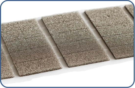
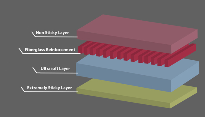
For easier assembly, as mentioned in the Hardness part, you could have fiberglass reinforcement carrier to strengthen the handling capability, minimize the tolerance and endure with punch pressure from pins on board. It’s available for adding it in the middle and on the surface. One-side / two-side additional adhesives can be achieved when required for pre-attachment.
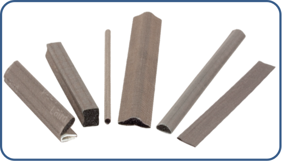
Back to the designs, it may appears various kinds of gaps and shapes for applying the thermal gap fillers. Especially for irregular gaps like vertical angular one, normal thermal pad may not be perfectly fit for this occasion. Then thermal putty will be your substituted option instead. However, as thermal putty is a semi-liquid material and will flows when shaking if the gaps is over 1.0mm, our pre-cured thermal putty pad will be right there for solving this issue, which is capable of 1.0-4.0mm thick range.
Dielectric Insulation / Breakdown Voltage
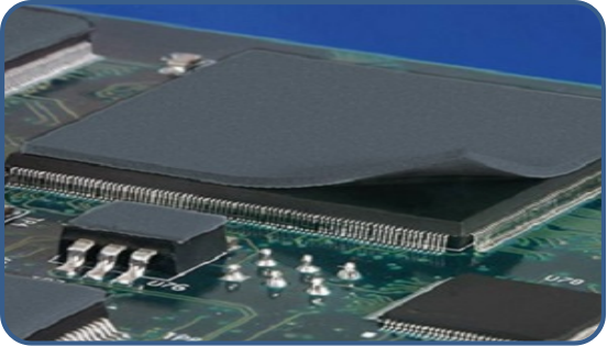
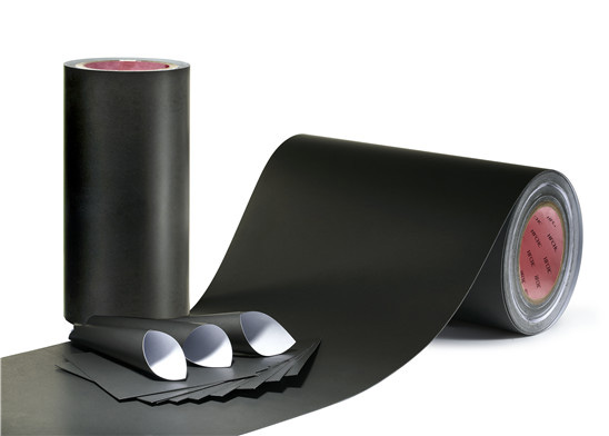
The TIP Series Thermal Pad
The TIP series is yet another of Lintech’s enhanced thermal gap-filling materials that provides extreme thermal conductivity and thus unparalleled thermal interface resistance for board level multiple component thermal management. It is designed to provide conformability and compressibility to bridge the thermal gap of large boards and sensitive components. It is non-phase changing and will not contaminate components.
Main Thermal Pad Material Types Seletion
| Typical Properties of SinoGuide Thermal Conductive Pad | ||||||||||
| Properties | Units | TCP100 | TCP150 | TCP200 | TCP300 | TCP500 | TCP600 | TCP750 | TCP110U | Test Method |
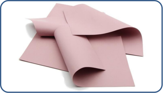
| Color | --- | Gray | Black | Dark Gray | Blue | Pink~Violet | Light Blue | Violet | pink/white | Visual |
| Reinforcement Carrier | --- | — | — | — | — | — | — | — | Fiberglass | --- |
| Thickness Range | mm | 0.25~15 | 0.25~15 | 0.25~15 | 0.25~15 | 0.25~15 | 0.3~10 | 1.0~10 | 0.5~10 | --- |
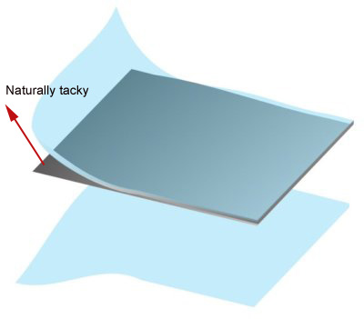
| natural tacky (1- or 2-sided) | --- | 2 | 2 | 2 | 2 | 2 | 2 | 2 | 1 | --- |
| Hardness | Shore C | 25,35 | 15,25,35 | 15,25,35 | 25,35 | 30 | 30 | 50 | 5, 15 | ASTM D2240 |
| Density | g/cc | 1.8 | 2.2 | 2.4 | 2.6 | 3 | 3.6 | 3.8 | 2.0 | ASTM D792 |
| Continuous Use Temp | ℃ | -40 to 200 | EN344 | |||||||
| ELECTRICAL | ||||||||||
| Breakdown Voltage | Kv/mm | ≥9 | ≥9 | ≥9 | ≥6.0 | ≥6.0 | ≥6.0 | ≥6.0 | ≥6.0 | ASTM D149 |
| Volume Impedance | ohm-cm | ≥4x10¹² | ≥5x10¹² | ≥3.6x10¹³ | ≥1.1X10¹⁴ | ≥1.1X10¹⁴ | ≥6.5X10¹⁰ | ≥6.5x10¹⁰ | ≥6.2X10¹⁵ | ASTM D257 |
| Dielectric Constant | 1MHz | 5.27 | 5.2 | 6 | 6.8 | 6.6 | 6.5 | 6.8 | 5.5 | ASTM D150 |
| Flame Rating | --- | V-0 | V-0 | V-0 | V-0 | V-0 | V-0 | V-0 | V-0 | UL 94 |
| THERMAL | ||||||||||
| Thermal Conductivity | W/m.k | 1.0 | 1.5 | 2.0 | 3.0 | 5.0 | 6.0 | 7.5 | 1.1 | ASTM D5470 |
Note: "D" suffix: one side tacky and non-tacky on the other side
"A1" suffix: Additional adhesive on one side, "A2" suffix: Additional adhesive on both sides
"M" suffix: Fiberglass reinforcement in the middle layer for all the size if required
"F" suffix: Fiberglass reinforcement on top or bottom layer
Standard sheet: 200x400mm,300x300mm,Custom configuration Available